Capacitive Touchscreen Technology (CTP) dominates the Human-Machine Interface (HMI) field. It offers excellent sensitivity, durability, and multi-touch capability. Therefore, high-value markets use it widely. This includes consumer electronics, industrial control, smart cars, and smart medical devices. This report focuses on Projected Capacitive (PCAP) technology. I will detail its industrial-grade manufacturing process.
I. Introduction: Capacitive Touch Technology Basics and Industrial Positioning
1.1 Capacitive Touch Technology Principle: From Surface Capacitive to PCAP
Touchscreen technology has evolved. It started with Resistive, moved to Surface Acoustic Wave (SAW), and then to Capacitive. Resistive screens sense input using mechanical pressure. They show lower light transmission and durability. SAW technology uses piezoelectric transducers. These transducers emit an ultrasonic network. SAW offers clear images but is sensitive to surface contaminants.
PCAP technology stands out because of its superiority. Earlier Surface Capacitive systems used the human body’s static charge. However, these systems usually offer only single-point touch. They also fail when the operator wears gloves.
PCAP is an improved solution. It embeds a transparent electrode film and an IC chip into glass or film layers. The PCAP sensing mechanism works like this: It measures mutual capacitance changes between interweaving driver (Tx) and receiver (Rx) electrode arrays. This pinpoints the touch location. When a finger or conductive object touches the screen, it disrupts the local electric field. This causes mutual capacitance to change. The controller IC then calculates the precise 2D coordinates based on these changes.
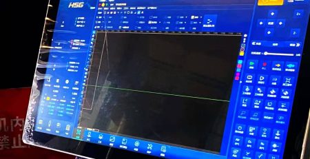
PCAP’s core advantages include multi-touch support, high image clarity, scratch resistance, and high durability. Surface contaminants like dust, liquids, and grease do not affect it. Importantly, PCAP’s high sensitivity allows operation through thick cover glass. This feature is crucial for industrial settings where operators must wear gloves.
1.2 Structural Decomposition of the Touch Panel Kit (TP Kit)
A complete industrial-grade Touch Panel (TP) kit generally contains four main functional layers :
-
Cover Glass: This is the outermost layer. It provides physical protection, scratch resistance, and high surface hardness. It also ensures good light transmittance.
-
Touch Screen Sensor: This contains precision-patterned conductive layers. Examples include ITO or metal mesh. This layer detects the touch signal.
-
Optical Bonding Layer: Manufacturers use an Optical Clear Adhesive (OCA) or liquid resin (OCR). They fill the air gap between the sensor and the display module.
-
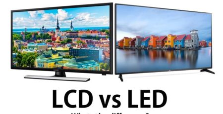
TFT LCD/Display Module: This module provides image output. It may use LCD, LED, or OLED technologies.
Industrial manufacturing focuses on integrating the separate sensor (input) and display (output) using precise processes. They then achieve high-precision, high-response interaction through a control circuit.
1.3 Strict Requirements for Industrial Manufacturing (IK10 Standard and Outdoor Environments)
High-reliability, high-value applications demand strict standards. These applications include Electric Vehicle (EV) charging station HMIs, industrial HMIs, and smart medical devices. They require much more than consumer electronics.
-
IK10 Impact Protection: Screens must withstand vandalism or accidental impact in public, unattended, or extreme operating environments, like industrial sites. The IEC 62262 standard defines the IK10 rating. This is the industry benchmark. It means the device resists 20 joules of impact energy. Manufacturers achieve IK10 by using advanced protection. For example, they use tempered cover glass, often between 4 mm and 10 mm thick.
-
Outdoor Readability: Outdoor applications require extremely high optical performance. This ensures clear readability even in strong sunlight. Industrial displays usually require a minimum brightness of 1000 cd/m². Displays frequently exposed to sun should ideally reach 2000 cd/m².
-
Environmental Resistance: Industrial-grade touchscreens must have high ingress protection (IP) ratings, such as IP65 or IP66. They must resist various contaminants and liquid intrusion. Furthermore, they must operate reliably over a wide temperature range, for example, from -40°C to +50°C.
II. Capacitive Sensor Core Component Manufacturing (Sensor Fabrication)
Sensor manufacturing forms the core of PCAP technology. It involves micron-level precision patterning. This process directly affects product performance and yield rate.
2.1 Substrate and Conductive Layer Material Selection
Sensor manufacturing first requires selecting the right substrate and conductive materials.
-
Substrate Types:
-
Glass Substrates: Manufacturers mainly use these for OGS (One Glass Solution) or G/G (Glass-Glass) structures. Glass provides structural rigidity and durability.
-
Flexible Films: Examples include polyimide (PI) film or PET film. They are used for G/F/F structures or flexible display technologies.
-
-
Conductive Materials:
-
Indium Tin Oxide (ITO): This is a traditional transparent conductive material. The process is mature, and it offers good light transmission.
-
Metal Mesh: This uses extremely fine silver or copper lines to build the conductive network. Metal mesh technology works well for large-sized touchscreens. Its low sheet resistance helps maintain signal transmission speed.
-
Metal mesh technology has advantages in large-scale applications. However, it negatively affects the display quality. This impact is especially noticeable with high-resolution displays. Metal mesh can reduce the display’s light transmission. Moreover, it can form Moiré effects with the display pixels. This severely degrades visual quality. Therefore, the manufacturing process requires complex optimization in pattern design and subsequent bonding steps. This helps mitigate the interference.
2.2 Key Step One: Cleanroom Environment and Photolithography Pre-treatment
Sensor circuit lines measure only a few micrometers wide. Even tiny particles can cause short circuits or open circuit defects. Consequently, the manufacturing environment needs extremely strict control.
-
Cleanroom Standards: Sensor manufacturing must occur in an ultra-clean environment. Purification engineering usually requires a cleanliness level up to Class 1 Standard. This extremely high cleanliness level is necessary for high-precision photolithography and etching. It guarantees high yield rates and product reliability.
-
Substrate Cleaning: Before patterning, the substrate surface undergoes multiple cleaning steps. These steps use high-purity water and chemical reagents. This completely removes organic and inorganic contaminants. It ensures good, uniform adhesion for subsequent conductive materials, like ITO or copper film.
2.3 Key Step Two: Conductive Layer Patterning (Photolithography and Etching)
Patterning creates the interweaving Tx/Rx electrode arrays. These arrays are essential for sensing touch. They must be accurately placed on the conductive film or substrate. The industrial standard uses photolithography combined with wet etching.
2.3.1 Detailed Steps for Photolithography and Wet Etching
-
Photoresist Coating: Manufacturers uniformly coat liquid photoresist onto the conductive layer. For example, they coat the outer copper film layer of a PET-ITO-copper composite material.
-
First Exposure and Development: Workers perform Ultraviolet (UV) exposure based on the preset electrode pattern. Development then removes the exposed or unexposed photoresist areas. This forms the photoresist layer that protects the copper electrodes.
-
Copper Etching: An acidic etchant, the copper film etching solution, etches the exposed copper film area. This builds the main structure of the Tx/Rx electrode array.
-
ITO Etching: Next, an ITO etching solution etches the underlying ITO film. This creates the critical mutual capacitance nodes and transparent connection areas.
-
Second Exposure and Development (Secondary Patterning): Workers perform a second exposure and development on the copper film. This step refines the circuit structure.
-
Second Copper Etching: The process uses the copper film etching solution again. This second etch significantly reduces the copper electrode linewidth. It boosts the sensor’s transparency (light transmittance) and touch performance.
-
Stripping: Finally, workers completely remove all remaining photoresist layers. The precisely patterned conductive layer remains. Sensor fabrication is now complete.
2.3.2 Importance of Process Control
Patterning ITO and copper composite materials presents a challenge. In traditional etching, the copper film easily corrodes during ITO etching. This leads to line width expansion or circuit structure damage. Therefore, using multiple exposures and precise etching steps—as described in the cited patent—is a key industry technology. It resolves linewidth control and yield issues. Accurate linewidth control enhances transparency. Furthermore, it guarantees the stability of the electrode network and the accuracy of the touch signal.
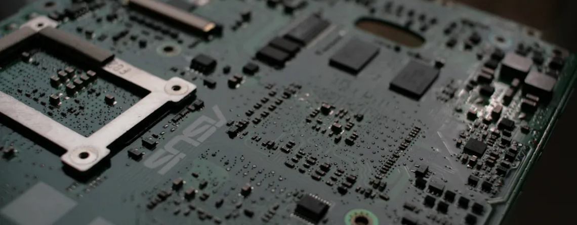
III. Flexible Circuit and Control System Integration (FPC & IC Integration)
After sensor patterning, the sensing signals must exit through a flexible circuit. They then connect to the touch controller. This allows signal processing and coordinate calculation.
3.1 Flexible Printed Circuit Board (FPC) Connection and IC Bonding
Leads on the touch sensor connect to the Flexible Printed Circuit Board (FPC). They use an Anisotropic Conductive Film (ACF) or a soldering process. The FPC transmits the signals. Moreover, it carries a dedicated integrated circuit (ASIC) for the touch controller.
Manufacturers use two main IC integration technologies:
-
COG (Chip-on-Glass): The IC chip bonds directly to the sensor glass substrate.
-
COF (Chip-on-Flex): The IC chip bonds to the FPC circuit board.
The bonding process typically uses heat pressing or ultrasonic technology. This ensures high stability and reliability for the electrical connection between the IC and the FPC or glass. During quality control, technicians test the impedance at these COG test points or bonding locations. This confirms the bonding quality meets requirements.
3.2 Touch Controller ASIC Signal Processing and Reliability Design
The touch controller ASIC critically determines touchscreen performance. It acquires the weak mutual capacitance signals from the Tx/Rx array. Then, it executes complex algorithms for noise reduction and coordinate calculation. The IC must resist electromagnetic interference (EMI) in industrial environments. EMI is an inherent weakness of capacitive technology.
3.2.1 Multi-Controller Collaboration and Redundancy Design
Large-sized or high-reliability industrial systems, like critical HMIs, may use two or more touch controller ASICs. These handle the touch signals. This multi-controller design does more than simply increase processing power. It involves a complex signal distribution and processing architecture.
In this advanced design, the receiver (and/or driver) circuits of the two or more touch controller ASICs connect to the touchscreen electrodes in an interleaved manner. This interleaved connection provides spatial redundancy for sensor data acquisition.
Crucially, these ASICs do not exchange raw mutual or self-capacitance data during the measurement frame. Instead, a processor—possibly a main processor—determines the final touch coordinates. It bases this calculation on all subsets of coarse touch coordinate data received from each ASIC.
This architecture offers two massive advantages:
-
System Redundancy: If a single ASIC or a section of electrodes fails, the system still uses data subsets from other ASICs. It can still determine the touch point. This guarantees the continuous reliability that industrial applications require.
-
High Efficiency and Low Latency: This method transmits only calculated “coarse coordinate subsets.” It avoids transmitting large volumes of “raw capacitance data.” This greatly reduces data bus bandwidth demands and latency. It ensures fast response under high load, such as multi-touch, meeting the speed and reliability requirements for industrial control and automotive HMIs.
IV. Module Optical Bonding and High-Reliability Packaging (Optical Bonding & Ruggedization)
Optical Bonding integrates the sensor with the display module. It gives the product industrial-grade durability and improves outdoor performance. It is a decisive step.
4.1 Optical Bonding Process Flow
Traditional displays use Air Bonding. This leaves an air gap between the screen glass and the LCD panel. Optical bonding fills this air gap.
-
Bonding Materials: Manufacturers mainly use Optical Clear Adhesive (OCA) in film form, or Optical Clear Resin (OCR), a liquid glue.
-
Industrial Bonding Steps:
-
Precision Cleaning: Workers thoroughly clean the cover plate, sensor, and TFT LCD surfaces. This prevents any dust or impurities from remaining.
-
Dispensing/Laminating: In a high-grade cleanroom, high-precision equipment (e.g., with ±0.1mm accuracy) dispenses the OCR or laminates the OCA.
-
Vacuum Bonding: The cover plate/sensor presses accurately onto the display module in a vacuum environment. This minimizes bubble generation.
-
Defoaming and Curing: The module undergoes Autoclave processing. This removes micro-bubbles. Then, UV light or heat cures the adhesive. This hardens it into a solid optical layer.
-
4.2 Key Technological Advantages of Optical Bonding (Industrial Applications)
Optical bonding is not just for aesthetics. It is a structural prerequisite for achieving industrial-grade performance. It offers irreplaceable advantages, especially in five areas :
-
Enhanced Outdoor Readability: Non-optically bonded screens have an air gap. The difference in refractive index between the air gap and the materials causes reflection when external light passes through. This results in a mirroring effect and reduced contrast. The optical bonding agent’s refractive index is similar to glass. This effectively reduces light reflection. It increases light transmission and contrast. Therefore, the display remains clearly readable even in strong outdoor sunlight.
-
Improved Durability and Impact Resistance: The hardened adhesive acts as a shock absorber between the glass and the LCD. This greatly increases the display’s resistance to pressure, impact, or vibration. Combined with thick tempered glass, optical bonding provides the structural foundation for achieving the IK10 (20 joules) anti-vandalism rating.
-
Safety Assurance: The optical bonding agent securely holds broken glass fragments even if the cover glass breaks accidentally. This prevents scattering. This feature is crucial for operational safety in harsh environments, such as public places, medical equipment, or factories.
-
Dust and Moisture Protection: Optical bonding eliminates the air gap between glass layers. This effectively prevents dust and moisture intrusion. It solves the fogging issue common in traditional screens in humid or outdoor environments. This ensures long-term display stability.
-
Increased Touch Accuracy: Light refraction angles in air-gap bonding can cause parallax. This makes the finger’s actual position and the corresponding point on the LCD visually misaligned. Optical bonding removes the air gap. This eliminates parallax. It provides a more accurate, natural, and reliable touch experience.
4.3 IK10 Design and Large-Size Challenges
Achieving IK10 protection poses engineering challenges, especially for large screens. The cover glass must become thicker to resist the 20-joule impact. This increases material cost, module weight, and manufacturing difficulty.
This challenge leads directly to market-driven optimization in industrial display size selection. For the EV charging station market, the 10.1-inch screen is mainstream. It achieves the best balance between size, readability, IK10 durability, and cost. Conversely, ultra-large screens, 15.6 inches and up, have high IK10 protection manufacturing costs. The market accepts them only if the manufacturer can monetize them commercially, such as through Digital Out-of-Home (DOOH) advertising. Therefore, screen size selection balances technical feasibility, durability cost, and commercial profitability models.
V. Quality Control, Testing, and Final Calibration (QC & Calibration)
After assembling the touchscreen module, it must pass rigorous quality inspection and calibration. This ensures its performance and reliability meet industrial standards.
5.1 Electrical and Structural Quality Inspection
Product quality inspection starts with fundamental electrical characteristics and structural integrity:
-
Electrical Test: Technicians use specialized point pressure testers. They check the sensor’s conductive lines for open circuits, short circuits, or leaks. They also check the uniformity of sheet resistance. Moreover, they test the bonding quality of the IC chip and the FPC circuit board. They evaluate connection reliability by testing the impedance of the COG/COF test points.
-
Optical Defect Inspection: Under high-intensity light, technicians strictly check the optical bonding layer (OCA/OCR). They look for defects like bubbles, foreign objects, delamination, or streaks. Any optical defect severely affects display quality and outdoor readability.
-
Structural Durability Test: The product undergoes IK impact testing (e.g., IK10) and IP protection testing (e.g., IP65/IP66). This simulates mechanical stress, vibration, and moisture ingress in the actual working environment.
5.2 Touch Function and Performance Testing
Functional testing focuses on evaluating the quality of user interaction:
-
Sensitivity and Linearity: Testers evaluate the touchscreen’s signal response at different pressures and touch speeds. They ensure the accuracy (linearity) of the touch trajectory.
-
Response Time: They measure the time from touch signal generation to system processing completion. This ensures real-time smooth operation and prevents lag.
-
Multi-touch Performance: Testing confirms the screen’s recognition accuracy, stability, and anti-interference capability for multiple simultaneous inputs.
Manufacturers can use a test method that overcomes machine errors. This improves test accuracy: They place a Golden Sample (a screen with known test results) in the point pressure tester. They measure its standard value. Then, they compare the measured value of the screen under test to this standard value. This method eliminates test errors caused by factors like the point pressure tester’s mechanical position error. It guarantees consistent quality judgment across different sizes and specifications of touchscreens.
5.3 Final Calibration and System Optimization (Calibration)
The final calibration step maps hardware performance to software and user experience:
-
Coordinate Mapping: This ensures the physical touch point position accurately corresponds to the pixel coordinates on the display.
-
Professional Color Calibration: For high-end or specialized applications, such as smart medical devices or graphic workstations, display calibration requires fine-tuning. This matches specific brightness, gamut, and color targets.
-
Spectroradiometer Calibration: For extremely demanding displays (e.g., Apple Pro Display XDR), manufacturers can use a spectroradiometer for “Full Calibration.” This recalibrates the display. It ensures the final display output for color and brightness meets strict professional standards.
VI. Summary and Future Trends Outlook
6.1 Summary of Key Industrial Manufacturing Challenges
Manufacturing Projected Capacitive touchscreens is a high-investment, high-precision, high-barrier system engineering project. The main challenges include:
-
Cost and Technical Barriers: PCAP manufacturing requires Class 1 ultra-cleanroom environments, complex multi-step photolithography and etching processes, and expensive optical bonding procedures. This makes its manufacturing cost significantly higher than earlier resistive technologies.
-
Yield Rate Control: Any environmental or process parameter fluctuation can cause defects during micron-level conductive line patterning. Therefore, conductive line yield and IC bonding defects are critical factors affecting overall manufacturing cost and efficiency.
-
Reliability vs. Size Conflict: As screen size increases, the required cover glass thickness and structural complexity grow geometrically to maintain the IK10 impact resistance level. This demands strong structural design and optical bonding capabilities from the manufacturer.
6.2 Touchscreen Technology Frontier: Transitioning to the “Smart Hub.”
Future touchscreens will move beyond simple input devices. They will become “Smart Hubs” that integrate multiple interaction modes. Technology development focuses on three main areas:
6.2.1 Haptic Feedback and High-Reliability Operation
The spread of touchscreens in smart car dashboards highlights safety issues. Frequent screen glances while driving risk driver distraction. Therefore, manufacturing actively integrates Haptics technology (tactile feedback). Powerful haptic feedback simulates the feel of physical buttons, bumps, or depressions. This allows users to identify and operate virtual buttons by touch alone. They can perform “blind operation.” This significantly improves driving safety in high-reliability scenarios.
6.2.2 Flexible Display and Spatial Form Factor Breakthroughs
Flexible display technology breaks traditional rigid display limitations. It moves from bendable and foldable forms toward more imaginative stretchable forms. Industry experts define the stretchable elastic flexible display as the ultimate form of flexible display. It achieves 2D or even 3D deformation in any direction. Ultimately, it aims to achieve the ambitious vision of “every surface is a screen.” This requires unprecedented breakthroughs in materials, panel structure design, and process technology.
6.2.3 Multi-Modal Collaborative Interaction Ecosystem
Future touchscreens will become core interaction systems that integrate Artificial Intelligence (AI). Single interaction modes, like touch or voice, have limitations. Therefore, the future trend involves multiple modalities working together. This includes touch, voice control, gesture recognition, and eye-tracking technology.
AI-driven Intelligent User Interfaces (IUI) sense user intent and context. They seamlessly switch and coordinate multiple interaction modes. In this ecosystem, the touchscreen acts as a coordinator. Users can use voice to wake the device, gestures for navigation, and the touchscreen for precise input and parameter adjustment. Together, they build a more natural, efficient, and seamless human-machine interaction ecosystem. Furthermore, non-contact technologies, such as suspended touch sensors and ultrasound, are being developed for public health needs. They offer hygienic alternative interaction solutions for touchscreens.
6.3 Conclusion and Outlook
Capacitive touchscreen manufacturing is a complex, multi-stage process. High-precision photolithography and etching, distributed IC architecture, and optical bonding technology are key steps. They ensure the product achieves industrial-grade reliability and high performance. Companies targeting high-value markets succeed by offering customized, integrated solutions. They must rely not only on simple technical parameters but on structural design and process innovation (like achieving the IK10 rating). They must also integrate vertical market needs (like haptic feedback for automotive and DOOH integration for EV charging stations). Future manufacturing will focus on closely linking technological innovation with user experience and environmental endurance. This shifts the role from a hardware supplier to an integrated solutions provider.
We hope you found these touchscreen or panel PC fundamentals informative. Goldenmargins offers a broad selection of Industrial Touchscreen Monitors and Touch Panel PCs in various sizes and configurations, including medical-grade touch screens, sunlight-readable touch screens, open-frame touch screens, and waterproof touch panels, as well as other unique touchscreen or panel PC designs. You can learn more about our services here or by calling us at +86 755 23191996 or sales@goldenmargins.com.